Mfr Part # ATMEGA88PA-AUR
IC MCU 8BIT 8KB FLASH 32TQFP
Microchip Technology
License: Attribution-NonCommercial-ShareAlike AM / FM Radio Arduino
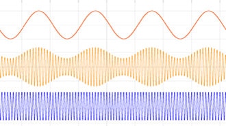
Without a doubt, FM transmitters and Receivers are among the top favorite electronic project topics, however, building a digital FM transmitter can be a challenging project for electronics enthusiasts. The transmitter can then be connected to a source of audio, such as a phone or computer, to broadcast music or other audio content.
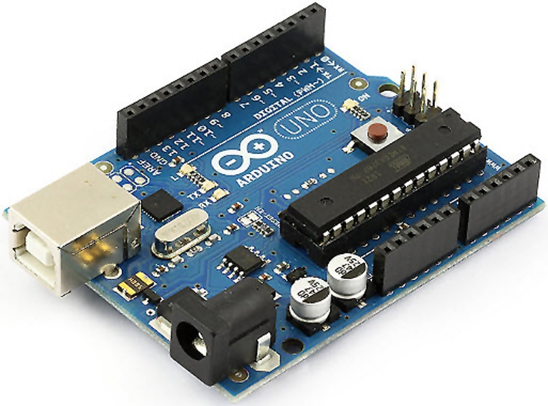
In this project, I have introduced a compact stereo digital FM transmitter circuit that operates in the frequency range of 87MHz to 108MHz. The frequency can be adjusted using two tactile push-buttons, with a 0.1MHz step size. The heart of the circuit is an ATMega8 microcontroller, which communicates with a 0.96-inch SPI OLED display and the KT0803L FM transmitter chip via an I2C interface. You can directly connect a microphone or an AUX cable to the board to broadcast your desired sound, such as playing a piece of music from your cellphone, computer, … etc. After conducting some tests, it was found that the circuit operates quite stable, and the received sound is clear and sharp.
To design the schematic and PCB, I used Altium Designer 23 and shared the project with my friends to get their feedback and updates using Altium-365. I am confident that utilizing this circuit will be an enjoyable and fulfilling experience for you.
Specifications
Input Voltage: 7-9VDC
Current Consumption: 50mA
Frequency Range: 87MHz to 108MHz
Frequency Step Size: 0.1MHz
AUX Input: Stereo
A. Circuit Analysis
Figure 1 shows the schematic diagram of the digital 87MHz to 108MHz FM transmitter. It consists of several parts which I explain one by one.
Figure 1, Schematic diagram of the digital FM transmitter project (Altium)
A-1: Power Supply
P2 is an XH connector to apply power to the board. The input voltage could be something between 7-9VDC. FB1 and C11 build a lowpass filter to reduce input noises. REG2 is the TLV1117-5.0 [1] regulator to prepare the +5V voltage rail. C12 and C13 are used to stabilize the output voltage of the regulator and reduce noise. REG1 is the TLV1117-3.3 regulator [2] to prepare the +3.3V voltage rail. D1 is an LED to indicate the proper supply connection and C10 and C14 are used to stabilize the output and reduce the noise.
A-2: Microphone Input
P1 is an XH connector to connect your electret microphone to the board. C8 is a decoupling capacitor to reduce the noise and R6 prepares a supply rail for the microphone. C9 removes the signal DC element and Q1 [3] amplifies the weak microphone signals to be delivered to the FM transmitter chip.
A-3: Logic Level Converter
T1 and T2 are 2N7002 N-Channel Mosfets [4] that are used to convert the 5V I2C logic level from the microcontroller (U2) to the 3.3V logic level to be applied to the FM Transmitter chip (U1). R2, R3, R7, and R8 are pull-up resistors to complete the circuit.
A-4: FM Transmitter
The main component of this part is the KT0803L chip (U1) [5]. S1 is an SMD headphone jack used to connect an AUX cable to the board. This allows you to transfer sound from your mobile phone, PC, or other device to the board. C5 and C6 are used to transfer the acoustic signal to U1. C2 and C3 are decoupling capacitors, and ANT is a UFL connector that provides an interface for your telescopic antenna to the board.
A-5: Microcontroller and Display
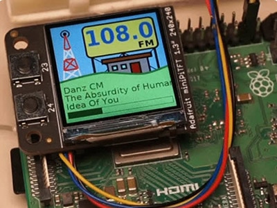
The heart of the circuit is the ATMega8-AU microcontroller (U2) [6]. C15...C18 are decoupling capacitors to reduce the noise. R10 is a pullup resistor for the RESET pin. LCD is the SPI 0.96-inch 128*64 OLED display, as shown in Figure 2. C19 is a decoupling capacitor for the supply pin of the LCD. SW1 and SW2 are tactile pushbuttons to increase and decrease the frequency. C20 and C21 are used to debounce the pushbuttons and r11 and R12 are pullup resistors. ISP prepares the necessary AVR-ISP pins to flash the MCU. Although not mandatory, you may choose to solder a pin header in place.
Figure 2, A picture of the 0.96-inch 128*64 Yellow-Blue SPI OLED Display
B. PCB Layout
Figure 3 shows the PCB layout of the design. It’s a two layers PCB board and almost all components are SMD. Figure 4 shows the board assembly drawings.
Figure 3, PCB layout of the digital FM transmitter project
Figure 4, Board assembly drawings of the digital FM transmitter project
C. Code and Programming
If you just want to build the project, the same way as it is, simply download the HEX file from here [7] and program the microcontroller. Set the MCU Clock Fuse Bits to 8MHz, Internal.
If you plan to modify the code, below is the MCU code for the Arduino platform. Make sure to add this FM library [8], this SPI OLED library [9], and the MiniCore board manager library [10] to your Arduino IDE. Set the clock source on Internal, 8MHz.
#include <FMTX.h>
#include <SPI.h>
#include "SSD1306Ascii.h"
#include "SSD1306AsciiSpi.h"


#define CS_PIN 7
#define RST_PIN 9
#define DC_PIN 8
#define Down_Key 15
#define UP_Key 14


float frequency = 87.0;
float tolerance = 0.001;


SSD1306AsciiSpi oled;


void setup() {
  fmtx_init(frequency, EUROPE);
  oled.begin(&Adafruit128x64, CS_PIN, DC_PIN, RST_PIN);
  oled.setFont(Adafruit5x7);


  pinMode(Down_Key, INPUT);
  pinMode(UP_Key, INPUT);


  oled.clear();
  oled.set2X();
  oled.println("   FM-TR   ");
  oled.setRow(3);
  oled.setCol(40);
  oled.set2X();
  fmtx_set_freq(frequency);
  oled.println(frequency, 1);
}


void loop() {
  if (digitalRead(Down_Key) == 0 && frequency > 87.0) {
    delay(130);
    frequency = frequency - 0.1;
    fmtx_set_freq(frequency);
    if (frequency < 100.0) {
      oled.setRow(3);
      oled.println("           ");
      oled.setRow(3);
      oled.setCol(40);
      oled.println(frequency, 1);
    }
    if ((frequency - 100.0) >= -tolerance) {
      oled.setRow(3);
      oled.println("           ");
      oled.setRow(3);
      oled.setCol(35);
      oled.println(frequency, 1);
    }
  }
  if (digitalRead(UP_Key) == 0 && frequency < 108.0) {
    delay(130);
    frequency = frequency + 0.1;
    fmtx_set_freq(frequency);
    if (frequency < 100.0) {
      oled.setRow(3);
      oled.println("           ");
      oled.setRow(3);
      oled.setCol(40);
      oled.println(frequency, 1);
    }
    if ((frequency - 100.0) >= -tolerance) {
      oled.setRow(3);
      oled.println("           ");
      oled.setRow(3);
      oled.setCol(35);
      oled.println(frequency, 1);
    }
  }
}
D. Assembly and Test
Soldering the components should not be an issue, as the smallest package size is 0805 or the UFL connector. However, if you do not have the time or experience to assemble the board, you may choose to order a pre-assembled board instead. Figure 5 displays the assembled board.
Figure 5, Assembled board of the digital FM transmitter project
E. Bill of Materials
Figure 6 shows the bill of materials for the project.
Figure 6, Bill of Materials for the digital FM transmitter project