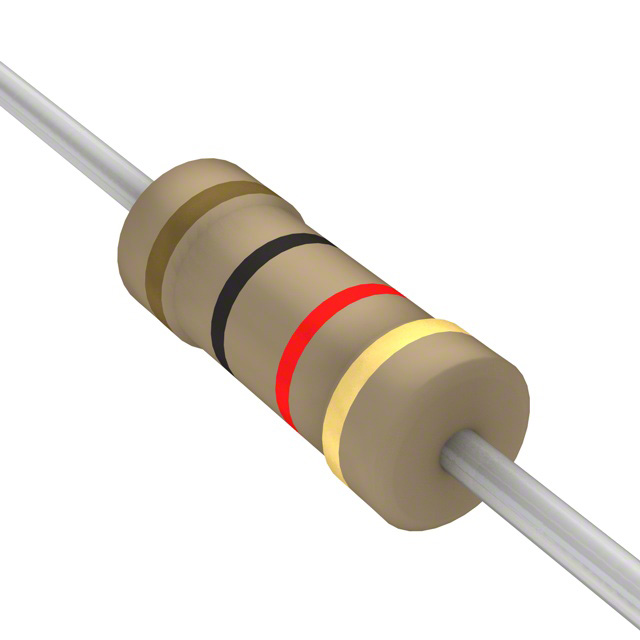
Mfr Part # CF14JT100R
RES 100 OHM 5% 1/4W AXIAL
Stackpole Electronics Inc
License: See Original Project Capacitors Diodes Resistors Transistors LEDs / Discrete / Modules
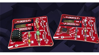
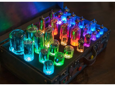
A color organ, also known as a light organ, visually represents sound by synchronizing changing colors with the sound. It translates sound (or music) into visual effects. Basic electronic circuits can be built that filter audio frequencies to determine which lights should be activated. Specific colors and/or light patterns can be assigned to different tones or ranges. The image below shows some color organs from the 1970s.
A retro color organ. Source.
In this project, a combination of high-pass, low-pass, and bandpass capacitive filters light up different LEDs based on the frequency of the sound. The approach combines the light drivers with the filter stage to simplify the design and reduce the parts list, making it inexpensive to implement. This project is based on LED Color Organ Triple Deluxe: 4 Steps (with Pictures)—Instructables.
What is a Color Organ
Color organs have been around for many years. They create highly dynamic, synchronized light shows that enhance the sensory experience of music and sounds. These devices can be standalone or integrated into larger systems, such as stage lighting or multimedia installations. In the 1960s and 1970s, electronic color organs became essential to many music performances, adding dimension to the music being heard.
Modern color organs can involve complex interactions between code and hardware, but simpler ones can be built with standard circuitry components, a source for the audio, and a 9V battery.
Parts List
There are a total of 32 parts in the BOM (Bill of Materials) as listed below:
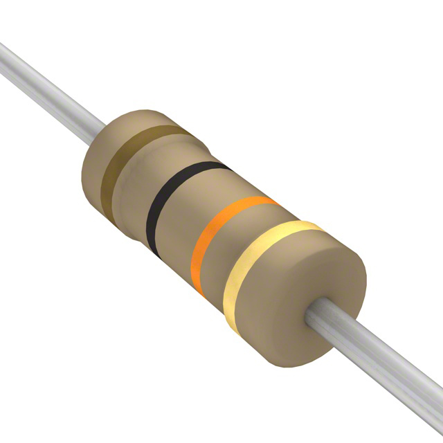
Resistors:
Capacitors
Transistors
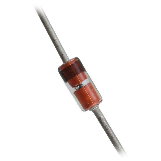
Diodes: 1x 1N4148 diode
Breadboard with assorted jumper wires
Audio: stereo headphone cable
Power: 9V battery and connector/holder
If you need help identifying the resistors, try DigiKey's 4 Band Resistor Color Code Calculator. They also have an RC and RL Passive Filter Calculator.
You can find the circuit diagram for this project below. The first filter is the high-pass filter, the second is the band-pass filter, and the third is the low-pass filter. Note that diode D1 is 1N4148 or equivalent, transistor Q1 is 2N2222A (or equivalent), and transistors Q2 through Q4 are all 2N2907A (or equivalent). Transistors Q2, Q3, and Q4 serve to amplify and switch the LEDs on or off based on the signal from their respective filters.
Circuit diagram for the simple color organ.
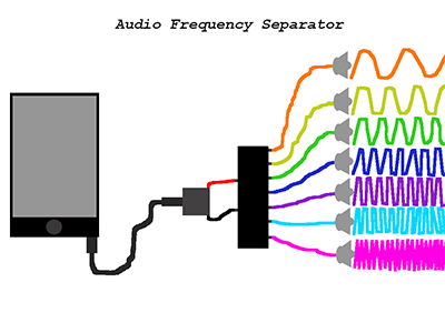
How This Retro Color Organ Works
The color organ works in a very straightforward manner: the audio signal is boosted by an amplifier and then passes through three filters. Each filter connects to a transistor and LEDs. Here are the approximate frequency cutoffs for the filters in the project:
Low: less than 72.34 Hz
Mid: between 72.34 Hz and 1.54 kHz
High: greater than 1.54 kHz
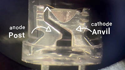
Notice that the formulas for these filters are related to fc, the cutoff frequency, and to R and C (Resistance and Capacitance, respectively). In short, fc = 1 / (2𝛑RC), which means that you can change the cutoff by modifying R and/or C. Below, you can see the high-pass filter's resistance and capacitance, and the resulting cutoff frequency.
High pass filter. Source.
Low pass filter. Source.
Next, the circuit passes through a band-pass filter, Filter 2. Filter 2 combines Filter 1 and Filter 3 in series. Only the middle-range frequencies of the audio are allowed to pass through and activate the green LEDs. Finally, Filter 3 only allows the low frequencies to pass through and activate the red LEDs.
How To Build the Circuit
Step 1
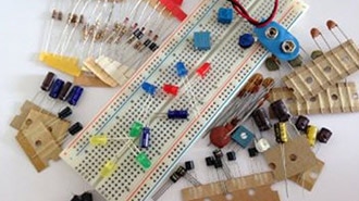
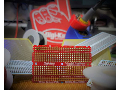
Verify that you have all the needed parts, including wire cutters and a breadboard. The recommended setup for the power is shown below, but the battery should not be connected until the circuit is complete.
Breadboard setup with power.
Step 2
Let’s move on to the audio input for the circuit. The audio signal comes from a set of basic stereo headphones. When you cut the headphone cord and strip it, you see three wires: two carry the audio signal (left and right), and one connects to the ground. The three wires in this project are shown in the previous circuit diagram, where the gold wire connects to ground. The input from the headphones is connected to the circuit with two 100Ω resistors all in parallel.
Individual wires in a stereo headphone line.
Step 3
Now assemble the far left of the circuit, shown below. The diode D1 is 1N4148 or equivalent, and transistor Q1 is 2N2222A (or equivalent). The current from this part of the circuit flows to Filters 1, 2, and 3.
The initial portion of the circuit.
Step 4
The next step involves assembling the filter and LED circuits. Note that you can set up the LEDs in a different order; just make sure they still have the appropriate resistor after the LED. Also, note that transistors Q2 through Q4 are all 2N2907A (or equivalent).
Detail of the filter and LED portion of the circuit.
Modifications
This basic circuit can be modified in many ways. For example, you can increase or decrease the number of groups into which the frequencies are divided. You can also change the LED colors and the number of LEDs and modify the individual filters by adjusting the resistance and/or the capacitance. In addition, a more permanent circuit than a breadboard can be assembled and placed in a wooden enclosure to complete that vintage feel.
Conclusion
Color organs are still fun to build, whether simple designs, as shown or more complex designs using addressable LEDs. This project demonstrates a simple yet effective approach to building a color organ: a combination of high-pass, low-pass, and band-pass filters translates audio frequencies into a dynamic light show. This retro project provides a fun and engaging way to experience music and offers a valuable learning opportunity in electronics and circuit design—with no expensive, unusual components needed.