Compact Multiband Patch Antenna Simplifies Design of RF Front-End for GNSS Receivers
Contributed By DigiKey's North American Editors
2025-10-23
Inspired by the successful commercial launch of the Global Positioning System (GPS) in the United States in the late 1980s, many other countries worldwide have also developed and launched their respective GPS versions, which are collectively known as the Global Navigation Satellite System (GNSS). In the past 25 years, GNSS technology has evolved to play a critical role in the interconnected world. Today, GNSS includes the European Union’s Galileo, Russia’s GLONASS, China’s BeiDou, India’s IRNSS/NavIC, and Japan’s QZSS. To work with multiple satellite constellations, a GNSS receiver system uses multiband frequencies to offer better accuracy and reliability than traditional GPS receivers, which use only the GPS satellite system.
Because an antenna is a key component of a receiver, it plays a crucial role in capturing weak radio signals from the satellites to determine the user’s precise position, navigation, and time. As a result, a GNSS receiver uses multiple frequency bands that correspond to both the lower and upper radio frequency (RF) bands transmitted by different satellite navigation systems in space. The bands and frequencies covered by GNSS receivers are summarized below:
- L1, E1, B1 bands cover a frequency range of 1,559 MHz to 1,610 MHz
- L2, E6, B3, L6 bands cover a frequency range of 1,217 MHz to 1,300 MHz
- L5, E5, B2, L3 bands cover a frequency range of 1,164 MHz to 1,217 MHz
Accordingly, GNSS receivers utilize a wideband or multiband antenna that can handle the multiple frequency ranges used by various satellite networks in space. Using multiple bands of frequencies allows the GNSS receiver system to offer improved positioning accuracy and reliability with reduced vulnerability to signal errors and interference, enabling GNSS antennas to deliver superior performance across broad and difficult environments.
Multiband patch-within-a-patch antenna
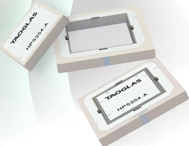
Because the initial GPS receiver systems employed large and bulky stacked antennas that occupied valuable real estate, the demand for a compact, low-profile solution has been high for the last several years. To efficiently and cost-effectively address the requirements of modern GNSS RF front-end modules, Taoglas Limited has designed and developed a superior antenna technology for the height-restricted, precise application. The company’s Inception Series HP5354.A is a multiband, 1,160 MHz to 1,610 MHz, passive patch antenna designed for improved position accuracy, robustness, and reliability. It uses an innovative ceramic patch-within-a-patch antenna technology that combines two antennas in the same form factor of a single-band GPS antenna (Figure 1). As a result, it guarantees optimized polarization gain for BeiDou (B1/B2a), GPS/QZSS (L1/L5), GLONASS (G1), and Galileo (E1/E5a) bands, including IRNSS/NavIC (L5). It also ensures compatibility with a wide range of applications, irrespective of location.
 Figure 1: The Inception Series HP5354.A is a low-profile dual-band patch-within-a-patch antenna for GNSS receiver systems. (Image source: Taoglas Limited)
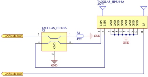
Optimized for dual-band performance, the HP5354.A is a compact, low-profile antenna that measures 35 mm x 35 mm in size with a height of 4 mm. Encased in an 11-pin surface-mount ceramic package, it uses three of its pins for capturing orthogonal radio signals from the L1 and L5 bands. Two of the pins are used for receiving signals from the L1 band, with the third one for the L5 band. The remaining eight pins serve as ground.
To obtain optimal axial ratio and right-hand circular polarized (RHCP) signal at the output, the two feeds for the L1 band are combined using a recommended hybrid coupler, the HC125A (Figure 2). Offering low insertion loss and balanced output amplitude, the HC125A comes in a low-profile (1.5 mm height) surface-mount package for multiband GNSS applications.
 Figure 2: The two feeds from the L1 band are combined in the HC125A hybrid coupler to ensure optimal axial ratio while creating an RHCP signal. (Image source: Taoglas Limited)
In addition, the dual-feed antenna has been tuned and tested on a 70 mm x 70 mm ground plane and has demonstrated excellent radiation patterns. Moreover, it has been fully characterized across both bands for key frequency-dependent parameters. These include return loss, voltage standing wave ratio (VSWR), efficiency, average gain, peak gain, axial ratio, phase center offset, phase center variations, and group delays.
With a low profile, the dual-feed antenna can be utilized in a wide range of applications where traditional stacked patch designs are too bulky and tall. Some of the recommended applications include navigation, industrial tracking, autonomous vehicles and robotics, as well as wearables, compact asset trackers, and precision agriculture.
Building the front-end RF signal chain
While the multiband GNSS antenna can be combined with a user-provided GNSS front-end, Taoglas has simplified the design of the signal chain using the TFM.100B GNSS front-end module, which is designed for use with multi-feed patches.
The module comprises a two-stage low-noise amplifier (LNA) that offers more than 25 decibels (dB) of gain across all bands and exhibits a low noise figure (NF) of less than 3 dB. It features a surface acoustic wave (SAW) filter that is combined with the LNA to craft a SAW/LNA/SAW/LNA topology that handles both the low-band and high-band signal paths to reject unwanted out-of-band (OOB) interferences from overdriving the GNSS LNAs or the receiver. The SAW filters within the TFM.100B have also been carefully selected and placed to provide excellent OOB rejection while maintaining the low 3 dB NF. This easy-to-integrate surface-mount device measures 20 mm x 18 mm and operates from a single 1.8 V to 5.5 V DC supply. A wide input voltage range enables the front-end module to be easily integrated into most GNSS receivers.
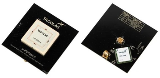
To further help users understand the integration of complete GNSS receiver front-end modules, Taoglas engineers have readied an evaluation board, the AHPD5354A (Figure 3), as a reference design for the front-end signal path. This evaluation board combines the TFM.100B preamplifier, the low-profile, high-performance HC125A 3 dB hybrid coupler, and the HP5354.A multiband patch antenna on a single printed circuit board (PCB).
 Figure 3: Taoglas’ AHPD5354A evaluation board simplifies the integration of a low-noise preamplifier, a 3 dB hybrid coupler, and a multiband patch antenna into a complete RF front-end module for GNSS receiver systems. (Image source: Taoglas Limited)
The evaluation board indicates that the hybrid coupler is required only when the GNSS band of operation is high (1,559 MHz to 1,610 MHz). Likewise, the board’s layout diagram suggests that the hybrid coupler must be placed close to the antenna pins and properly terminated using two 100 Ohm resistors in parallel.
Additionally, the board also highlights some of the benefits of using the TFM.100B GNSS front-end module. These include:
- An easy drop-in package with any antenna or GNSS receiver
- Integrated pre-filters that deliver exceptional OOB rejection across multiple bands and other neighboring interferences to achieve low NF
- Two-stage LNAs, pre-filters, and optimized impedance matching that provide sufficient gain to the GNSS receiver without signal-to-noise overload
- A compact footprint and low-profile design which save valuable real estate and require no external components and routing
- The highest level of integration, manufacturability, and robustness in a single compact package
Conclusion
A multiband patch antenna is an essential component of modern GNSS receivers for improving performance in challenging environments. By receiving radio signals from multiple frequencies across low and high bands, a dual-band antenna enables GNSS receivers to overcome the limitations of a single-band system. Toward that goal, Taoglas has developed a low-profile, dual-band antenna using novel patch-within-a-patch technology that concurrently supports the L1 and L5 bands in a small form factor. Combined with the company’s hybrid coupler and low-noise preamplifier with integrated SAW filter and impedance matching circuit in a compact ceramic package, the result is a high-performance RF front-end signal chain solution for GNSS receivers.

Disclaimer: The opinions, beliefs, and viewpoints expressed by the various authors and/or forum participants on this website do not necessarily reflect the opinions, beliefs, and viewpoints of DigiKey or official policies of DigiKey.


