Set Temperature, Actuator Responds – Arduino LCD Shows Live Temp & Statu
2025-11-12 | By Ron Cutts
License: GNU Lesser General Public License DC Motor Drivers / Controllers Motors Temperature Arduino ESP32 ESP8266
In this Visuino project, you will learn how to control a linear actuator automatically based on temperature (or humidity) readings using a DHT11 sensor, an I2C LCD, and an L298N DC motor driver. Set your desired temperature threshold, and the actuator will open when the temperature is higher than or equal and close when it’s lower. The LCD shows the current temperature (or humidity) and clearly displays the actuator status as Open or Closed—all without writing a single line of code!
This project is great for opening a window or door automatically based on the temperature, making it perfect for home automation, greenhouses, or any environment control application.
This is perfect for learning how to:
Read temperature and/or humidity from a DHT11 sensor
Control a linear actuator using an L298N DC Motor Driver
Display live sensor readings and actuator status on an I2C LCD
Create automated environment control projects with Visuino Visual Programming
Build practical projects like vents, windows, or humidity/temperature-controlled devices
Download the Visuino project file at the bottom
Watch the Video!
Step 1: What You Will Need


Arduino UNO (Or any other Arduino-compatible board)
LCD I2C Display (Optional)
Visuino program: Download Visuino
Step 2: The Circuit

Connect the power supply (batteries) pin (gnd) to the motor driver controller pin (gnd)
Connect power supply (batteries) pin (+) to motor driver controler pin (+)
Connect the power supply (batteries) pin (+) to the Arduino pin (VIN)
Connect the GND from the Arduino to the motor driver controller pin (GND)
Connect digital pin(3) from Arduino to motor driver pin (IN1)
Connect digital pin(4) from Arduino to motor driver pin (IN2)
Connect the linear actuator to the motor driver, as you can see on the schematic
Connect LCD Display pin [SCL] to Arduino pin [SCL]
Connect LCD Display pin [SDA] to Arduino pin [SDA]
Connect LCD Display pin [VCC] to Arduino pin [5V]
Connect LCD Display pin [GND] to Arduino pin [GND]
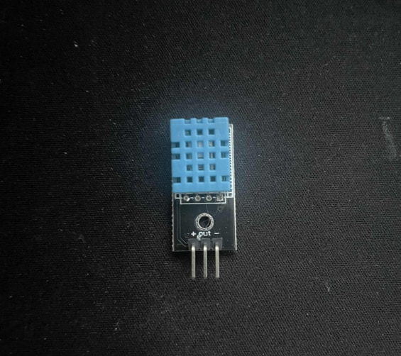
Connect DHT11 sensor pin[S] to Arduino digital pin[2]
Connect DHT11 sensor pin[-] to Arduino ground pin[GND]
Connect DHT11 sensor pin[+] to Arduino positive pin[5V]
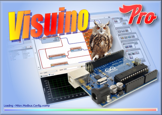
Step 3: Start Visuino, and Select the Arduino UNO Board Type


Start Visuino as shown in the first picture. Click on the "Tools" button on the Arduino component (Picture 1) in Visuino. When the dialog appears, select "Arduino UNO" as shown in Picture 2
Step 4: In Visuino Add Components


Add "Humidity and Thermometer DHT11/21/22/AM2301" component
Add "Analog Value" component
Add "Compare Analog Value" component
Add "Detect Edge" component
Add "Text Value" component
Add "Speed and Direction To Speed" component
Add "Dual DC Motor Driver Digital and PWM Pins Bridge (L9110S, L298N)" component
Add "Liquid Crystal Display (LCD) - I2C" component
Step 5: In Visuino Set Components


Select "AnalogValue1" and in the properties window set "Value" to 1 <<this will be the speed of the motor, you can adjust it, the minimum is 0 and the maximum is 1
Select "Compare1" and in the properties window set "Compare Type" to ctSmallerOrEqual and "Value" to 27 <<this is the temperature to compare, feel free to adjust this according to your needs
Select "DetectEdge1" and in the properties window set "On Rising/True" to False
Double click on the "TextValue1" and in the Elements window drag "Set Value" to the left side and in the properties window set "Value" to OPEN
Drag another "Set Value" to the left side, and in the properties window, set "Value" to CLOSED
Double click on the "LiquidCrystalDisplay1" and in the Elements window drag "Text Field" to the left side and in the properties window set "Initial Value" to TEMP: and "Width" to 5
Drag another "Text Field" to the left side and in the properties window set "Row" to 1
In the Elements window, drag "Analog Field" to the left side and in the properties window set "Column" to 7 and "Width" to 10, and "Precision" to 0 << These are temperature decimals. If you plan to use a sensor with decimal output, you can change this value
Step 6: In Visuino Connect Components
Connect "HumidityThermometer1" pin[Temperature] to "Compare1" pin[In]
Connect "HumidityThermometer1" pin[Temperature] to "LiquidCrystalDisplay1" > "Analog Field1" pin[In]
Connect "HumidityThermometer1" pin[Sensor] to Arduino digital pin[2]
Connect "AnalogValue1" pin [Out] to "SpeedAndDirectionToSpeed1" pin [Speed]
Connect "Compare1" pin [Out] to "DetectEdge2" pin [In]
Connect "Compare1" pin [Out] to "DetectEdge1" pin [In]
Connect "Compare1" pin [Out] to "SpeedAndDirectionToSpeed1" pin [Reverse]
Connect "DetectEdge1" pin [Out] to "TextValue1.Elements.Set Value1" pin [In]
Connect "DetectEdge2" pin [Out] to "TextValue1.Elements.Set Value2" pin [In]
Connect "SpeedAndDirectionToSpeed1" pin [Out] to "DualMotorDriver1.Motors.Item[0]" pin [In]
Connect "LiquidCrystalDisplay1" pin [I2C Out] to "Arduino.I2CChannels.I2C" pin [In]
Connect "DualMotorDriver1" > [Motors.Item[0].Direction] pin [Out] to "Arduino" pin Digital pin [4]
Connect "DualMotorDriver1" > [Motors.Item[0].Speed] pin [Out] to "Arduino" pin Digital > Analog PWM pin [3]
Step 7: Generate, Compile, and Upload the Arduino Code

In Visuino, at the bottom, click on the "Build" Tab, make sure the correct port is selected, then click on the "Compile/Build and Upload" button.
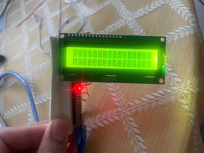
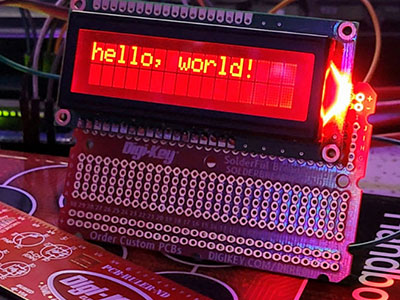
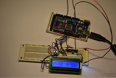
Step 8: Play
If you power the Arduino module and the Linear Actuator will start to move according to your settings for the temperature, and the display will show the current Temperature and Actuator status.
Congratulations! You have completed your project with Visuino. Also attached is the Visuino project that I created for this post. You can download it here and open it in Visuino: https://www.visuino.eu
Download: Linear-Actuator-DHT11-LCD.visuino
Download: Linear-Actuator-DHT11.visuino